
|
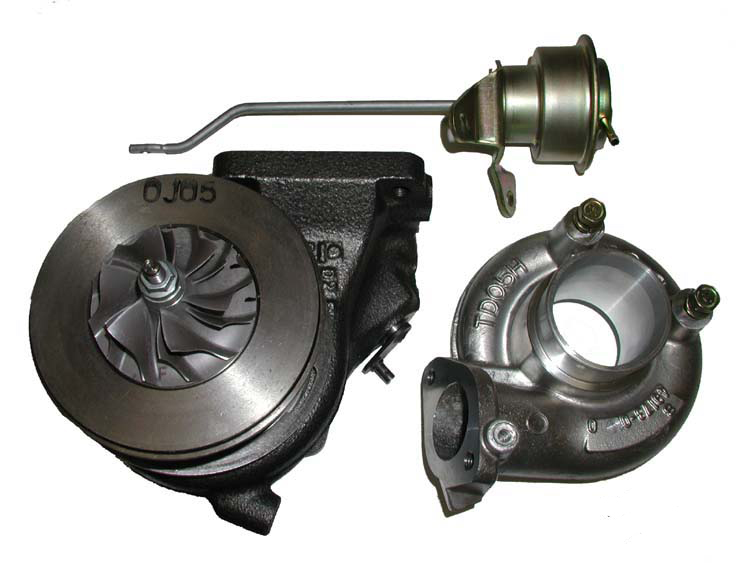
TD05H-14B Turbo This is info on the setup I have installed on my car. Currently it is using a TD05H-14B turbo from a DSM. This turbo, while from the factory, is quite a large turbo in comparison to many stock turbos. However, as you'll see in my current setup it isn't that great when running under 4psi like my current setup. This turbo likes to flow and likes to flow a lot. Now on to some info...
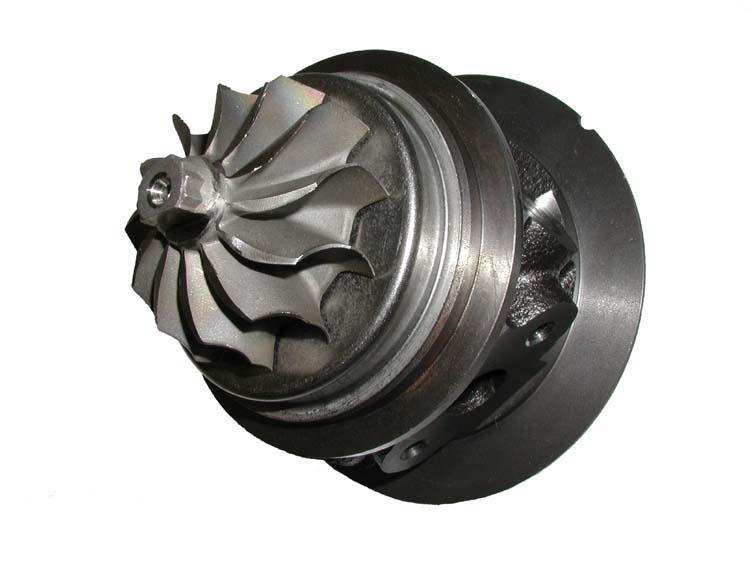
The main reason I chose the 14b was its prooven ability to make big power, the cheap cost of a used 14b, its durability, and the ease of upgrading to a larger turbo. The MHI turbos (14b, 16g, and 20g) are all solid performers each capable of being thrown on without replacing a thing. These numbers refer to the compressor wheel and the larger the number the more it flows. Generally, 16g's can make 350HP without a problem. 20g's over 400hp. Because they each can be used in the TD05h housing spool up is quite similar and quite quick. Right now I'm seeing full (~4psi) boost at 2200 rpms. However, between 2200 and 3000 there is very little power increase as the efficiency is not that great. I probably have more tuning that needs done but basically, power really doesn't hit till 3500 or so. This turbo pulls very very hard after 4000 and continues to pull without loss till fuel cut at 6500. This compliments the RS's power curve nicely where it tends to drop off up high when naturally aspirated.
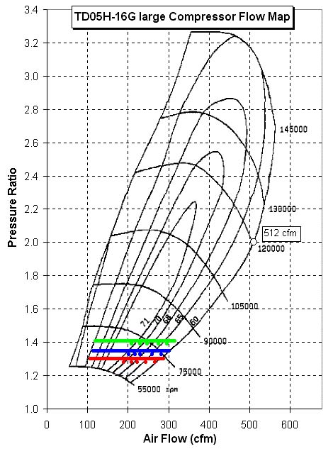
The compressor flow map for the 14b shows how inefficient the turbo is at 4psi. Bumping it up to 5psi it gets better. Things start falling into place around 6psi. These are all indicated by the lines on the compressor flow map. Red corresponds to 4, blue to 5, and green to 6 psi. For those that do not quite know how to read flow maps. The pressure ratio is the boost pressure in bar including ambient (1.0 bar). 1 bar is equivalent to around 14.7psi. So a 1.3 pressure ratio would equate to 4.43psi of boost. The row on the bottom shows how much airflow the turbo is producing. This is a function of the amount the engine (naturall aspirated flows) combined with the pressure ratio. Guesstimates about volumetric efficiency, or the ability of the engine to flow, are made to compute the flow data. The topographical map looking parts to the graph are the compressors efficiency at that given boost pressure and flow rate, obviously the higher the efficiency the better. This is because the colder the compressor outlet air is the more dense it is. The more dense the air, the more air molecules. The more air molecules the more power can be made. The rpm lines indicate the speed the turbo is spinning. By looking at the three plots on the compressor map you can see how the turbo will operate on the EJ25 engine at 4, 5, and 6 psi. The dots indicate 4000, 4500, 5000, 5500, 6000, and 6500 engine rpms. The efficiency helps give an idea of where power will best be made. THE REST OF THE SETUP As for the rest of my custom design I will show how I made the oil lines, uppipe, downpipe, intake piping, and intercooler. The gauges and electronics will be discussed in the tuning section. The first thing is the oil lines. I used a combination of stock DSM parts and steel braided lines to make the oil feed and return lines. The oil feed line uses -4AN steel braided hose and the stock DSM banjo fitting. Oil is supplied via the main gally oil plug located behind the alternator on the top of the engine. The Subaru plug is tapped for BSPT so I used a BSPT to NPT connector then an NPT to -4AN connector. The hose end was a 45degree hose end to clear the alternator. On the turbo side I cut off the feed pipe to leave about 2 inches before the banjo fitting. I then deburred and ground down the pipe so it would barely fit inside the hose. I then used a hose clamp to secure everything in place. As for the return hose. I used the stock DSM return pipe and cut it about 2 inches from the end. I deburred it and ground it down so -10AN steel braided hose would fit over it. A hose clamp with locktite was used to secure it against movement and engine vibrations. The return goes to the oil pan that was plumbed above and behind the drain plug. The -10AN hose uses a 45degree hose end to connect to the bulkhead fitting that I placed in the pan.
The bulkhead fitting as shown above uses a lock nut to secure it in place. The small end was cut off to allow easier flow of oil. The side with 2 sets of threads was on the outside of the pan. After drilling and dremeling a hole of approprite size I used a healthy helping of RTV sealant to ensure a good tight seal. I then cranked down the lock nut on the results can be seen in the image gallery. No leaks so far. The intake pipe uses the stock piece. I modified the stock MAF housing so that I could attach a K&N cone filter to it. The rest of the intake tract is from the stock flex hosing. I cut off the boner knob thing and used that for the BOV return hose. I drilled a hole and glued a pvc elbow into it for the PCV hose. Other than that I just used a 2"-3" silicone hose transition and hose clamps to secure everything. The compressor outlet pipe is a 2.5" pipe that was custom made at Monroe! I had them make a pipe, while i watched none the less, and weld on a flange for a 1g DSM BOV. The pipe fits perfectly with the turbo and the intercooler. The intercooler is from a Saab 900 Turbo. It is pretty small even for a top mount, but it does the job. It stays relatively cool on colder days and when moving. But it heat soaks almost immediately when sitting for any amount of time or hot days. To make it fit, I cut down the inlet end to make it straight. Otherwise it was bent back towards the engine and was almost impossible to get a pipe to connect to it. I used a 2.5"-2.5" silicone hose connector to connect the intercooler pipe to the intercooler. And a 2.5"-2.75" silicone transition to connec the IC to the throttle body. Good fit overall and definately better than no intercooler. As for the uppipe, it connects straight to the stock exhaust manifold and bends upward. The o2 sensor is almost right next to the flange. At the corner of the bend, right on the outter part of the bend is the Tial 35mm External Wastegate. This is set with a .3bar (4.3psi) spring. Because of the placement of the wastegate it starts to crack open before I really even hit boost. Once it opens it kind of sounds like a dentist suction tool at low rpms. Then it completely RIPS at high rpms. Deafeningly loud if you pass anything on the sides of the car and have the windows down. The down pipe connects off the back of the turbine and has the stock internal wastegate blocked off. It replaces the cats and connects back to the catback exhaust. Both pipes are 2" which will definately need to be changed. But it works for now.
|
|
|||